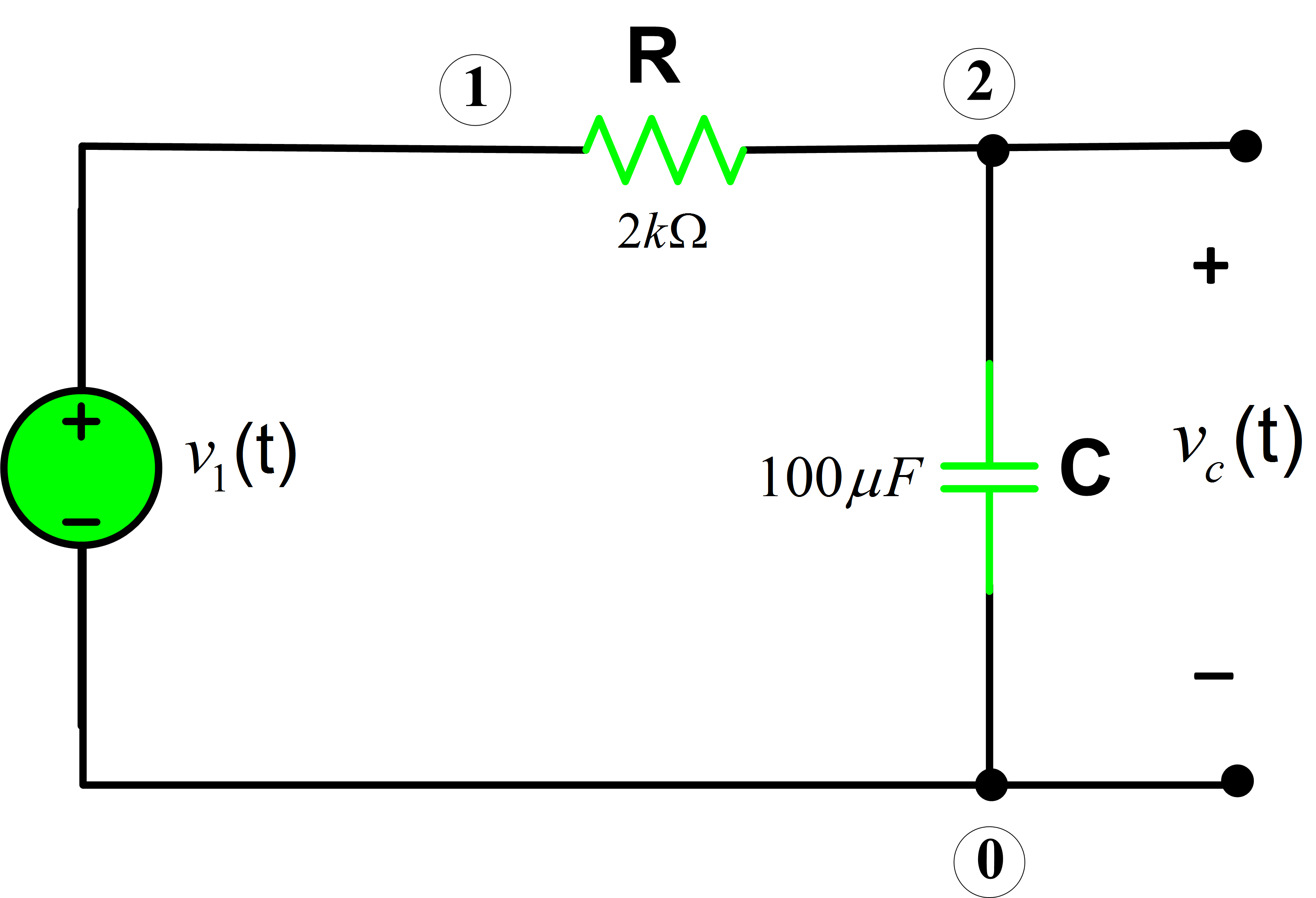
Capacitor Testing Circuit Diagram Pin On Capacitor Testing A
Circuit leakage test capacitors lets figure leak electronics lab edn measurements comments simulator Simple capacitor tester circuit Schematic illustration of the capacitor test structure showing ͑ a ͒
Capacitor Tester Circuit Diagram - Circuit Diagram
Capacitor circuit circuitlab test description Capacitor tester circuit diagram Electrolytic capacitor tester
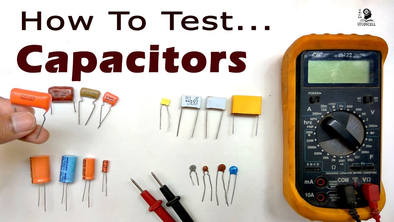
Test capacitors multimeter using without capacitor check circuits mylar capacitance measure digital circuit through board electronics ac types diagram choose
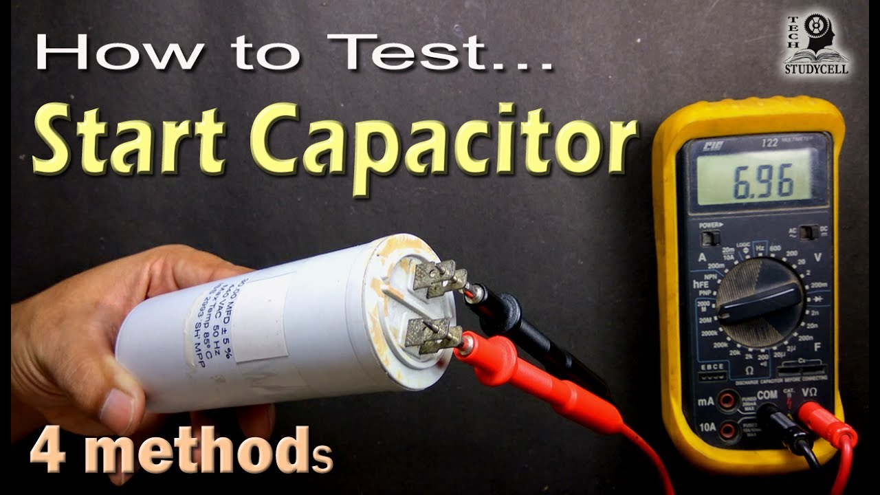
How to test motor start and motor run ac capacitor of ac fan andVector diagram circuit diagram capacitor tester stock vector (royalty Capacitor testing circuit diagramCapacitor motor start fan test ac run compressor.
Electrolytic capacitor test circuitCapacitor charging equation matlab voltage circuits electricalacademia Test capacitors capacitor multimeter ac using voltmeter electrical4u supply charge storing devices form most part electricalCapacitor multimeter capacitance measuring measure constant now electricaltechnology.
How to test a capacitor
Testing capacitorsHow to test a capacitor using digital and analog multimeter? Capacitor tester circuit diagramHow to test ac capacitor? the complete guide.
How to test a capacitor?How to test a capacitor: a complete guide Tester circuit capacitor diagram leakage seekic currentSimple_capacitor_tester.
Capacitor tester electrolytic circuit
Capacitor_testerCapacitor multimeter hvac blower spec sense Capacitor testCapacitor testing multimeter esr.
Capacitor testing circuit diagram3 phase capacitor bank wiring diagram Capacitor switching test circuit.Capacitor charging equation.

How to test a capacitor using digital and analog multimeter?
Capacitor test ohmmeter polarity saysCapacitor tester How to test a capacitor: a complete guideCircuit capacitor tester diagram simple seekic.
Continuity multimeter capacitor electricaltechnology components ohmmeter resistorHow to test capacitors with and without using multimeter How to test an ac compressor capacitorCircuit lets you test capacitors for leakage.

Testing capacitor using continuity
Pin on capacitor testing and esr resoursesHow to test ac capacitor with multimeter Capacitor multimeter capacitance checkingCapacitor tester circuit diagram » wiring diagram.
Capacitor test ac multimeter electrical4u connected voltmeter supply using follows procedure capacitorsHow to test a capacitor? Capacitor multimeter testing voltmeterCapacitor tester circuit diagram.
Electronic – how to test a capacitor – valuable tech notes
Test capacitor with digital meter .
.


